
 EN
EN
 ar
ar bg
bg hr
hr cs
cs da
da nl
nl fi
fi fr
fr de
de el
el hi
hi it
it ko
ko no
no pl
pl pt
pt ro
ro ru
ru es
es sv
sv tl
tl iw
iw id
id lv
lv lt
lt sr
sr sk
sk sl
sl uk
uk vi
vi et
et hu
hu th
th tr
tr fa
fa ms
ms hy
hy ka
ka ur
ur bn
bn mn
mn ta
ta kk
kk uz
uz ku
ku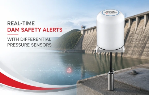
Real-Time Dam Safety Alerts with Differential Pressure Water Level Sensors
Key Takeaways An alert chain needs more than a sensor: define field in...

Inside a Load Cell Amplifier Circuit
A load cell puts out millivolt-level signals that easily drown in noise on the way to a DAQ. Without the right amplifier circuit, even a high-end sensor delivers useless data. Field engineers wrestle with gain drift, EMI, and zero offsets — problems that live in the analog front-end. Kingmach has spent years building geotechnical instruments, so we’ve seen these pain points across construction sites, dams, and underground monitoring networks. Our approach to the amplifier circuit focuses on three things: matching the input stage to the sensor impedance, keeping the noise floor down, and making gain setting straightforward enough to survive harsh installations. Different sensors demand different excitation voltages and output scaling, and a one-size circuit rarely holds up. The notes below walk through what makes a measurement chain stable and where we’ve seen the biggest improvements in field reliability.
Technical Detail
The amplifier circuit is the first active stage between a load cell and the rest of the monitoring system. Its job is to take a differential signal from the strain-gauge bridge — typically 0-20 mV — and scale it to a range that PLCs, loggers, or ADCs can read without further conditioning. Input impedance matters: too low, and the bridge loads unevenly; too high, and bias currents start pulling the offset. Kingmach amplifiers use differential inputs with common-mode filtering to keep 50/60 Hz interference out of the signal path before it ever sees a gain stage. For multi-channel setups, the circuit also handles cross-talk by isolating supplies and laying out ground planes to avoid shared return paths. Gain configuration tends to trip people up. Switches and jumpers are simple but drift-prone; precision resistors give better long-term stability. We often supply amplifiers with factory-set gains matched to a specific sensor’s rated output, cutting field errors at commissioning. Where the user needs adjustability, a solder-jumper or sealed DIP switch offers a middle ground between cost and reliability. A detail that’s easy to overlook is the excitation supply. The amplifier’s voltage reference usually drives the bridge, so any ripple here gets amplified with the signal. We regulate the excitation locally on the amplifier board so that long cable runs don’t degrade the measurement. Temperature compensation is handled passively by the bridge itself, but the amplifier can add its own drift if the gain-setting network is sensitive. Using low-TCR resistors keeps the readings consistent from winter mornings to midday heat. Beyond the schematic, packaging affects how the circuit holds up over time. Potted modules survive humidity and vibration far better than open-frame boards. Kingmach ships amplifier circuits in sealed enclosures when they’re destined for dam monitoring or tunnel convergence stations. Since every project wires sensors differently, we provide field-terminal diagrams and support teams that can walk a site engineer through the setup over a call. The goal isn’t just a clean circuit; it’s a measurement chain that still works five years later without a service visit.
News
Key Takeaways An alert chain needs more than a sensor: define field in...
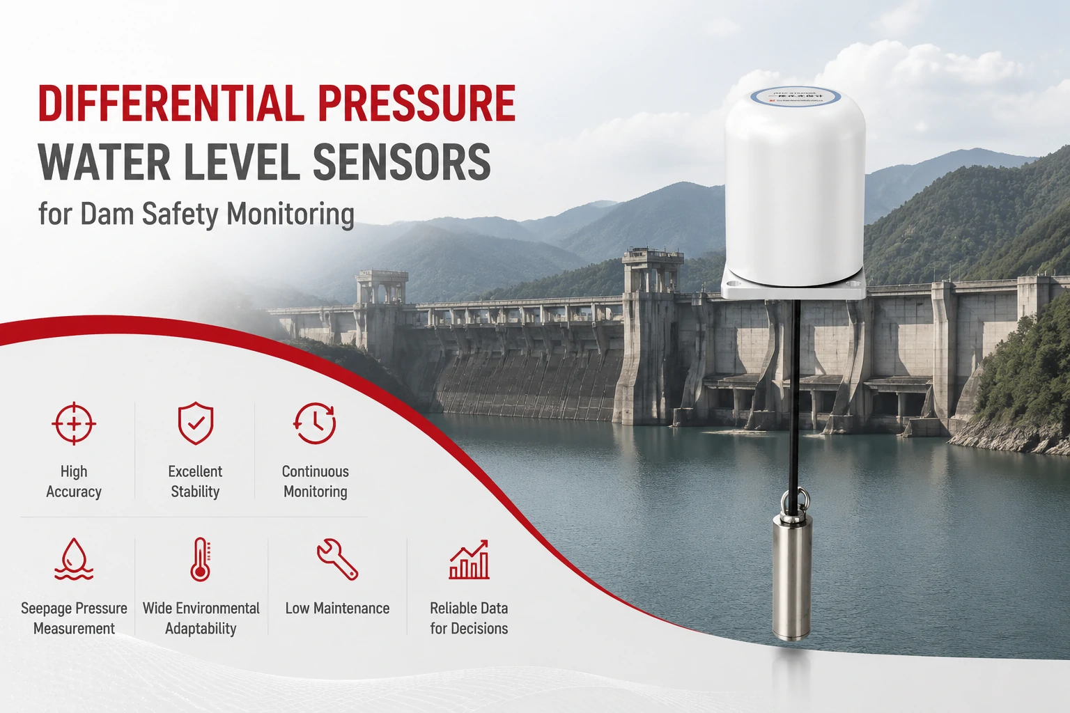
Key Takeaways The strongest fit is usually a confined, submerged, or s...
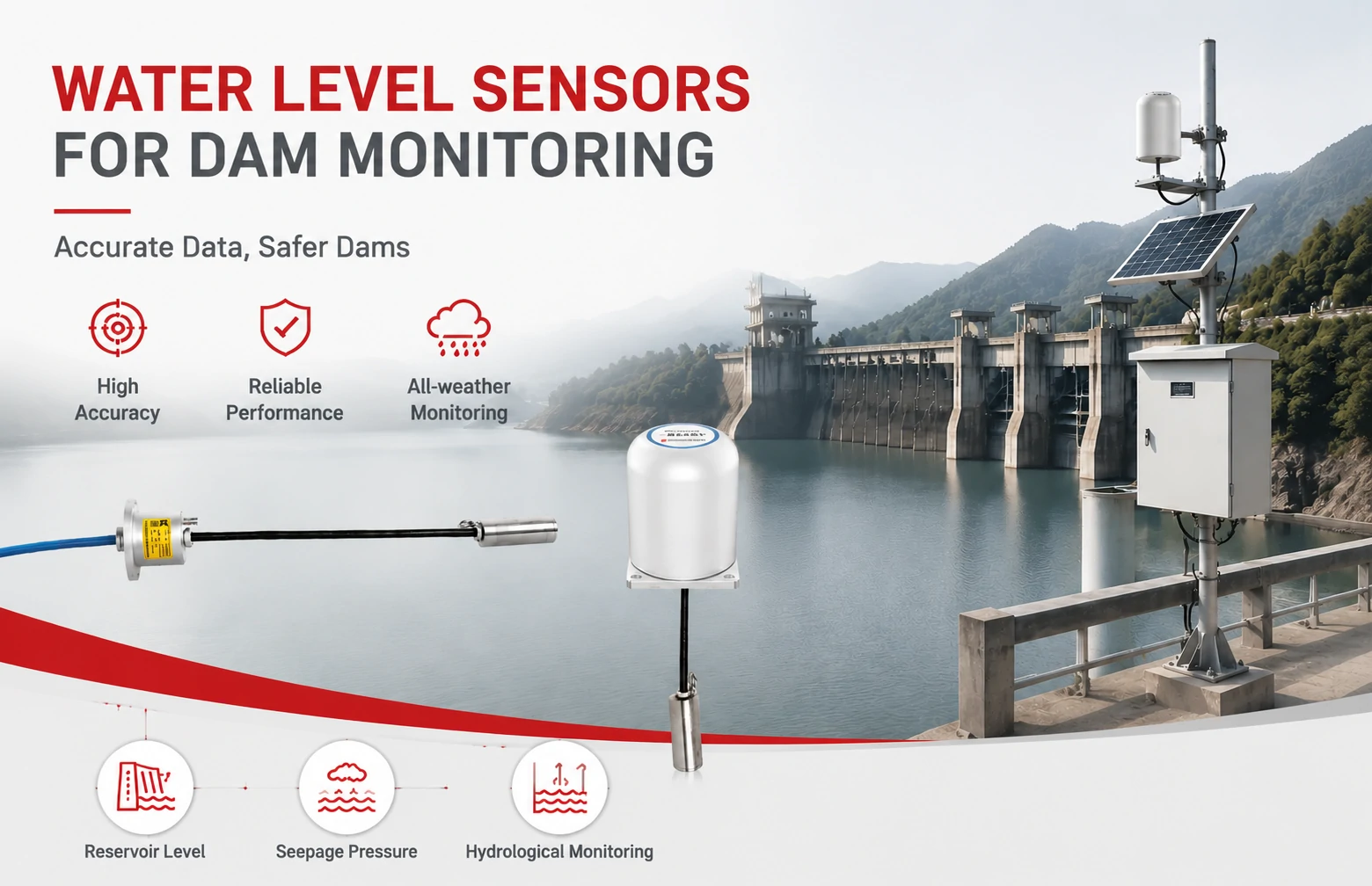
Kingmach Water Level Sensors for Dam Monitoring: A Buyer's Guide to Differential Pre...
Products
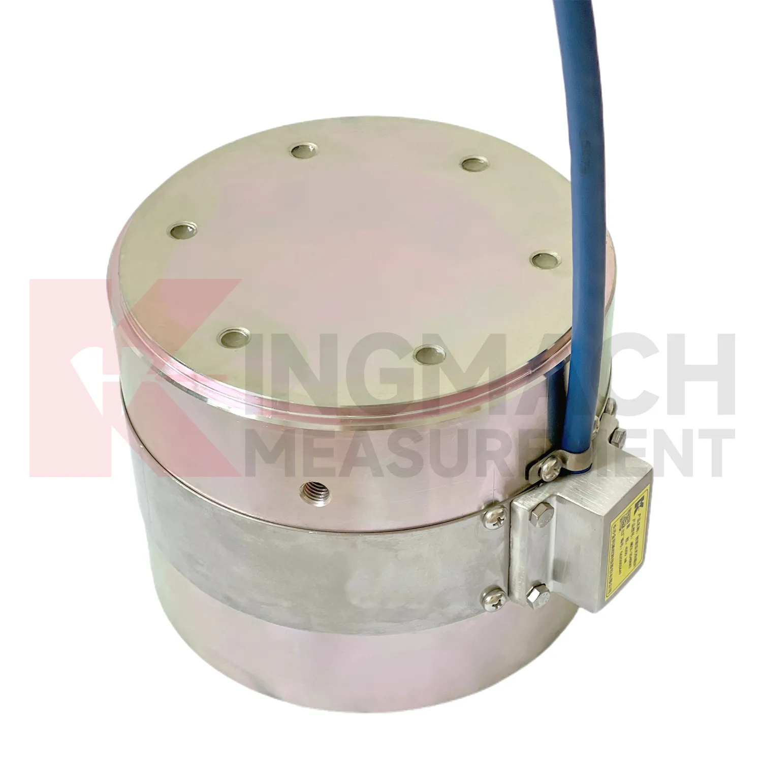
Solid load cell JMZX-34XXHAT、35XXHAT、36XXHAT
View Details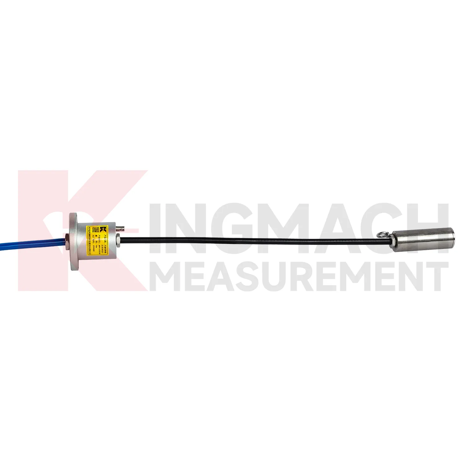
Wide-Range Smart Differential Pressure Water Level Meter JMYC-67XXAD
View Details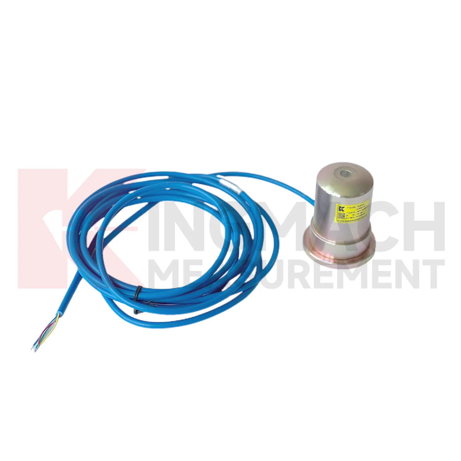
Smart Formwork Axial Force Meter(VW)JMZX-39XXHAT
View DetailsFAQ
It depends on the sensor’s rated output and the input span of the next stage. A 2-mV/V load cell at 10 V excitation gives 20 mV full-scale; to feed a 5 V ADC, you’d need a gain around 250. In practice, we often see gains between 100 and 1000, with lower values used for high-output sensors or where short cables keep signal levels up.
Three areas make the biggest difference: input filtering, ground layout, and shielding. A differential low-pass RC filter right at the amplifier inputs keeps out RF and high-frequency interference. Separating the analog ground from the power-supply return prevents digital noise from coupling in. And using a shielded twisted pair for the sensor connection, with the shield tied to the amplifier’s ground at one end only, creates a single-point reference that kills most common-mode hum.
You can, but you’ll usually need to match the excitation voltage and gain to each sensor. Strain-gauge bridges are fairly standard, but tall-column load cells and low-profile pancake types can have different impedance. Some circuits let you swap a resistor to adjust gain, and we can supply units with the gain set at the factory if you give us the sensor datasheet.
An onboard circuit shortens the analog path, so you get less noise and no worry about connector corrosion. But if the installation is tough to access, a separate amplifier near the logger can be easier to replace. For geotechnical jobs where sensors are embedded in concrete, we generally go with the sealed onboard approach.
Share your product type, target capacity, and application requirements. Our team can review the details and recommend a practical next step.
If you are interested in our products or want to become our partner.
Please leave your contact information, our team will contact you as soon as possible.
Mail: [email protected]
Contact Us: +8613808434127
Address: No. 188 Tongzipo West Rd, Changsha, Hunan, China